ICF versus Traditional Framing

From ICF Magazine.


*Please note that while Denver Concrete Vibrator does sell vibration equipment to consolidate concrete in Insulated Concrete Forms we do not sell the actual forms themselves.

WHAT ARE THE REAL COSTS OF USING ICFS?

All too often, we hear that ICF is more expensive than traditional methods. Within the industry, we hear percentages from 2% to 15% more to build than “stick”. Many times we hear that ICF is “not more expensive, just different”. Whether ICF is more expensive than wood frame is not something that can be stated in blanket terms for all geographical areas and every individual project. Pricing of labor and materials as well as building methods vary widely.

Every ICF professional should be aware of the variables that affect their market areas in order to discuss the ICF option with confidence. The cheapest price doesn’t always get the nod, many times, the educated buyer is sold by the knowledge of the salesperson. Do you know what the actual costs of ICF methods in residential construction are in your area? How do your costs for ICF compare with the traditional methods of wood framing for your area?

Here’s an example based on an “advanced frame and insulated home” in an area of Central Texas:
To keep this easy to follow, we’ll use a simple 3,000 square foot home. We’ll base this on the specifics of the particular market area, using local costs for labor and materials. Every reader of this column should run through the numbers and make adjustments to line items and costs using their local building costs and material requirements to learn the true cost difference between ICF and traditional methods for specific areas.

The customers words:
“We are building a 3000 square foot country style home (40×75) with four corners and porches on both 75 foot sides. This will be a single story 10′ wall height home, slab on grade. We expect that between 15 and 20 percent of our wall area will be windows and doors. We would like to build this home for $100.00 per square foot. We are concerned about energy, disaster resistance and overall strength of the home. What is the difference in cost between ICF and 2×6 frame with 4.5″ of open cell urethane foam insulation?”

First off, if ICF is an option, the homeowner must be advised that ICF is only one small piece of the building puzzle and that other complementary materials and methods must be used with the ICF option in order to make the ICF perform as they are hoping. If they decide on the ICF option, consideration needs to be given to the differences in better windows and doors, perhaps a sealed attic, embedded roof connections rather than anchor bolts and a top plate with toe nailed roof framing members.

Additionally, a properly sized HVAC system should be analyzed and finally, the impact on the foundation size, to name a few items can affect the costs. So, this $300,000 house could require more money to build. If the homeowner is already considering upgraded performance criteria for the house, these upgrades may already planned which would not impact the house cost with ICF walls. These items will not be used in the comparison, however, these items should be considered in every cost comparison.

The ICF specifications

  • #4 dowels, 48″ long, spaced 12″ on center.
  • 6″ ICF core.
  • Treated lumber window and door bucks.
  • #4 bar horizontal at 16″ on center and one within 12″ of the top of the wall, double at all openings.
  • #4 bar vertical at 12″ on center, double at all openings.
  • One #5 bar over all openings greater than 48″ with a minimum of 24″ lintel depth. Widest window is 72″.
  • 3/8″ aggregate 3500 psi concrete.
  • 36 meter boom pump required to place concrete.
  • Simpson strong tie hold downs will be used to anchor roof framing.
  • We will use $3.15 per sq. ft. of ICF for our ICF cost.
  • We will use $3.00 for ICF labor cost to include all subcontract cost of installation which would include General Liability Insurance, Worker’s comp, etc.
  • In Texas, all material costs have a tax of 8.25% added.

Estimating ICF Material and Labor:
Given 230 linear feet of wall. 2,300 gross sq. ft. of wall, figure 18% openings, however, In this example, we’ll figure the windows and doors solid and call the labor and material of the “bucks” a trade for formed wall area.

  1. Dowels: 230 pc, = 46 pc #4×20′ x$5.50, $253.00
  2. ICF forms, 6″ cavity @3.15/sq. ft., $7,245.00
  3. Reinforcing steel (.60 per sq. ft. with our schedule and $$), $1380.00
  4. Concrete at 80.00 per yard, $3407.00
  5. Concrete pump svc estimate, $600.00
  6. Miscellaneous items, etc., $250.00
  7. Embedded hold downs, figure about 75 @2.00, $150.00
  8. Labor to install @3.00 per sq. ft. includes all overhead., $6,900.00

Total cost of ICF installed on a slab with preset dowels:, $20,185.00

When it comes to framing, regardless of whether the home is an ICF or not, the typical framing subcontractor will not reduce the price of the framing bid because the ICF is installed. In this area, many framers want to add to the cost because they can no longer “just walk through the framing”, instead, they have to bring materials into the house via a window or door opening.

Framing contractors will typically charge based on the “covered area” and not necessarily by the square footage of the house. Normal framing subcontract costs in Central Texas for “decent” framing crews will run between $3.25 and $4.50 per sq. ft. of covered area. Keep this in mind since there is no labor deduction with an ICF wall home, we will not be deleting labor with the framing estimate, therefore, we won’t include it in the framing cost since presumably, the house will still require framing even though it is ICF.

Per the specifications set out earlier, the framing material costs are:

In summary comparison:
Looking only at the cost of the exterior walls of this home, it is obvious that ICF costs much more than wood frame. ICF, as a percentage, increases the cost of the exterior wall roughly two times (200%) the cost of the frame wall. (Consider that the homeowner would at least spend the initial $6537 for frame walls). A builder that is trying to dissuade a homeowner from going ICF would likely use the argument that ICF is over 3x the price of framing (6537×3=$19,611) which is a bit of a stretch since the homeowner is going to spend the $6,537 as a minimum and we’re talking about a small overall percentage of the cost of the total home.

When communicating the percent impact on the $300,000 home, the increase is approximately 5%. ($300,000 / $13648.00).

ICF and frame walls are not equal as we all know. I don’t believe that a frame wall has any advantage over ICF when it comes to performance, especially over the long term…

In most cases, the homeowner is the one that has already convinced themself that ICF “is the way to go”, they are only trying to determine the “cost/ value” in terms of building a new home with a limited budget. This is where the examples of utility savings, hurricane, fire and tornado and other durability marketing materials come into play.

For this example home, if the homeowner had already had ICF on the “want list” of materials, then presumably, other more efficient materials and methods were already considered so there wouldn’t be any other cost impacts of using materials and methods that complement the ICF product.

Return to Blog.

Read article at ICF Magazine.

ICF Intro

From ICF Magazine.

*Please note that while Denver Concrete Vibrator does sell vibration equipment to consolidate concrete in Insulated Concrete Forms, we do not sell the actual forms themselves.

ICF 101

As Insulated Concrete Forms (ICFs) become more common, a growing number of builders and concrete contractors are considering adding this skill set to their business. Additionally, do-it-yourself owner/builders are frequently attracted to ICF construction, as it provides a structure of exceptional quality at a reasonable price.

 With proper training, good bracing and correct concrete placement methods, it’s possible for just about anyone to build structures of outstanding beauty, durability, and energy-efficiency. For contractors already familiar with building codes, construction timelines, and concrete, it’s even simpler.

However, it’s not as easy as “stacking legos,” and even small mistakes can have disastrous consequences.

Training
For those new to ICF work, three items are essential: professional training, on-site guidance, and access to equipment. Otherwise, the finished project is likely to not look good, meet code, and/or have the required structural integrity.

The place to start is a training class offered in-person by a manufacturer’s representative. These are available in virtually every major city in North America. The American Institute for Architects offers AIA-accredited seminars geared towards teaching architects about ICFs. AIA-accredited seminars (or any other instruction that is classroom-only) are useful, but inadequate as stand-alone training. The prospective builder should insist on a hands-on training course that involves stacking the forms, installing bracing, setting window bucks, and so forth. It will take the better part of a day, at least. This kind of training seminar is usually free, although a few require payment (which is typically refunded with the first order of forms).

It’s best to follow-up on the course by working under the direction of a qualified professional for a few days. Often there are opportunities closer to home through programs like Habitat for Humanity. A week-long training course on a jobsite is optimal,
but rare.

For those planning on making ICFs a significant part of their business, the larger ICF brands offer advanced training on topics such as ICF sales and marketing, value engineering, bidding bigger projects, networking, contracts and construction management.

Getting Started
ICF work starts with accurate, dead-level footings. Any deviance in the footing from straight, level, or plumb will cause significant problems later, as ICF walls, when filled with concrete, will move so they are perpendicular to the surface. Bows or dips will also create hassles. If the footing is lower in the middle than at the corners, the wall will get tight as it goes up. If the footing is humped, the corners will be pushed out of plumb. The extra time (or money) spent to get dead-level footings will pay dividends the rest of the way up.

With footings in place, the outside edge of the walls is marked with a chalkline, noting all door openings. Then the first row (course) of forms is set into place, starting at the corners. The outside edge of this bottom course is fastened to the footing using either polyurethane foam, metal track, or sometimes lumber.

From there, the forms go up like brickwork, taking care that each form overlaps the one below it by half a length or so, and that the ties (webs) line up vertically. Most modern blocks are reversible, so corners can be flipped, but a few are not and have specific left- or right-hand corners. Horizontal reinforcing steel is added as the wall goes up. It simply sets in the rebar saddles molded into the form ties. If the engineer was good, he matched the rebar spacing to the height of the block.

For convenience, the joint/seam between the blocks (created by working from the corners to the middle) should be at either a door or a window opening. In some cases, the wall length will match the block interlock pattern perfectly. Otherwise, there will be a single seam running the full height of the wall that requires additional reinforcement.

Bucking
Set the window bucks as the wall goes up. Wooden bucks are the most common—they work well and are economical—but they’re not the only option. If wood is the choice, use only pressure treated lumber and/or exterior grade plywood. Two 2x4s on edge for the bottom of the window buck will create the gap for concrete placement. Nails hammered into the outside surface of the buck will ensure it stays locked into place after the pour.

Vinyl bucks are lightweight, termite-proof, and are superior for arched, gothic, or round windows.

EPS bucking systems offer better insulation values, but need extensive wooden reinforcement until the concrete sets. They can be site-fabricated from regular straight ICF forms by cutting the ties down the middle and ripping the panel to match the core width of the form. The cut half-ties anchor the bucks to the concrete; the furring strips provide attachment points for the window and door frames.

For large commercial work, steel “framing assemblies” combine the buck, frame, jamb, and finish flashings into a single component.

Regardless of the material, bucks need to be squared up and reinforced vertically and horizontally every 24″ on center to prevent sagging and blowouts. The bottom edge of window bucks need access ports to ensure concrete fills that part of the wall completely. Many find that building the bucks off-site will increase on-site productivity and keep the jobsite clean.

Bucks are secured to the wall with wire ties, reinforcing tape, or screws.

Bracing
Once walls reach three courses high (four feet) bracing is needed. While it’s possible to use wood, virtually everyone uses steel turnbuckle bracing, which allows the builder to make minor adjustments to the wall immediately after it’s filled with concrete. They also include an integral catwalk and safety rail.

For part-time or amateur builders, bracing can often be rented from the same establishment that sells the forms. Steel turnbuckle bracing such as Giraffe and Plumwall is durable, easy-to-use, and delivered in neatly organized crates. For those that can’t spare the expense, Fab-Form’s Zont allows the builder to create a adjustable bracing system from re-useable 2x4s assumed to be at the site.

Typically it’s one brace for every five or six feet of wall, with additional braces on each side of the windows, doors, and corners. A good rule of thumb is 32 units for a 1,500 sq. ft. basement.

Bracing is usually attached to the interior side of the walls. The strongback is screwed to the wall’s furring strips—just snug—ensuring the screw stays in the middle of the slot. This will allow for any movement that takes place.

Plumb the wall with a level, then stake the turnbuckle to the ground, or screw it securely to the subfloor.

Final Checks
With the walls at full height, weak points are reinforced with strapping tape, plywood, and lumber. Many brands need very little reinforcing. Those with thinner sidewalls sometimes need quite a bit. Radius walls, which are easy to stack, typically require extensive reinforcing. Other weak points are corners, lintels, and narrow columns. Some recommend using steel truss wire at the top of walls for added rigidity.

If the wall is continuing upward after the first pour, protect the form interlocks with packing tape.

If the form manufacturer’s recommendations are followed, bulges and blowouts are rarely a problem. It’s good practice to keep extra reinforcing materials on hand for pour day just in case.

Stretch a stringline from corner to corner on the outside of the wall to ensure the wall is straight and plumb. The wall should be about ¼ inch inside of plumb just before pouring, as it will shift outward when filled with concrete. If it doesn’t, it’s a simple matter to push it to the stringline with the turnbuckle.

The two most important points in an ICF build is when it comes off the footing, and the day of the pour. If the form distributor or ICF consultant has offered technical assistance, they should visit the jobsite and inspect every detail prior to pour day, checking the bracing, scaffold planks, wall reinforcement, bucking and so forth.

Take the time to carefully inspect every element of the wall prior to pour day. ICF construction is not forgiving. A wall with a typical 6” core will weigh about 1,000 lbs. per linear foot of wall, and if the wall is wavy or out-of-plumb due to inadequate bracing, or if there are bulges, blowouts or sagging lintels, good solutions short of tearing it out and doing it over are hard to come by.

Pour Day
Every form manufacturer specifies a mix for their brand of ICF. The local ready-mix plant may also have an ICF mix design that works well in the region. Typically, it’s a 3,000 psi mix with 3/8-inch aggregate and a slump of 5 ½ to 6 inches.

It is possible to fill ICFs without a pump truck, but a good boom pump truck with an experienced operator is so convenient and cost effective that it’s considered essential for ICF work. Traditionally, pumpers have used two 90º elbows attached to the end of the boom to slow the concrete down before it enters the forms. A few use a “ram’s horn” made from four elbows. Others prefer a reducing hose. Whatever the preference, make sure something is in place.

Schedule the pump truck to arrive at least an hour before the concrete. He’ll need the time to set outriggers, unfold the boom, and prime the pump. Trucks from the batch plant should be scheduled to arrive about 25 minutes apart.

Fill your openings—below window bucks and around doors—first to ensure good consolidation. Then work your way around the walls, filling the forms in four-foot lifts. If possible, avoid pouring concrete directly into the corners. Instead, hold the hose a few feet from the corner and let it gradually flow into place.

Vibration is essential. Most form manufacturers recommend a “pencil” vibrator with a head no larger than one inch in diameter. Oztec’s “stinger” vibrators and mechanical rebar shaker are a common option. The vibrator typically follows about six feet behind the boom operator. Insert the tip to the bottom of the lift (four feet, usually) and withdraw it slowly to give any trapped air enough time to escape.


Ironically, corners and lintels—the areas that need the most strength—are where poor consolidation is most likely to occur. That’s because these are the areas where reinforcing steel is most congested and ICF forms are at their weakest. Work these areas carefully to ensure good consolidation.

By starting with a good mix, placing it intelligently with a pump truck, and consolidating it carefully within the manufacturer’s guidelines, nearly all concrete placement problems can be avoided.

h

Before Becoming an Owner/Builder

  • Educate yourself about ICFs. – Is this something you can realistically do?
  • Choose a user-friendly block. Get as much training as possible beforehand.
  • Find a distributor committed to your success.
  • On the Jobsite, The Professional Should
  • Check the footing prior to being poured.
  • Ensure the first course of forms is plumb, level, and square.
  • Provide quality bracing as needed.
  • Inspect and correct deficiencies prior to each pour day.
  • Be on-site during pours.
  • Suggest subcontractors familiar with ICFs.

Return to Blog.

Read article at ICF Magazine.

Insulating Concrete Forms

icf block

*Please note that while Denver Concrete Vibrator does sell vibration equipment to consolidate concrete in Insulated Concrete Forms we do not sell the actual forms themselves.

Insulating concrete forms (ICFs) result in cast-in-place concrete walls that are sandwiched between two layers of insulation material. These systems are strong and energy efficient. Common applications for this method of construction are low-rise buildings, with property uses ranging from residential to commercial to industrial. Traditional finishes are applied to interior and exterior faces, so the buildings look similar to typical construction, although the walls are usually thicker.

Overview and History

Insulating concrete forms, or ICFs, are forms used to hold fresh concrete that remain in place permanently to provide insulation for the structure they enclose. Their history dates back to after World War II, when blocks of treated wood fibers held together by cement were used in Switzerland. In the 1940s and 1950s, chemical companies developed plastic foams, which by the 1960s allowed a Canadian inventor to develop a foam block that resembles today’s typical ICFs. Europeans were developing similar products around the same time.

In the 1980s and 1990s, some American companies got involved in the technology, manufacturing blocks and panels or planks. By the mid-1990s, the Insulating Concrete Form Association (ICFA) was founded to do research and promotion of the products, working toward building code acceptance. They also worked with the Portland Cement Association to build awareness of this type of construction. Although there were some obstacles—costs could be greater than frame construction because people didn’t understand the system, builders had to work closely to get code approval, and materials were proprietary—the number of insulating concrete forms producers grew. As a result, competition increased and costs moderated.

The new companies developed variations and innovations to distinguish one system from another. Over time, some ICF manufacturers consolidated, leading to a smaller number of larger companies. Because insulating concrete forms systems offered performance benefits like strength and energy efficiency and were initially more expensive to construct, the first target market was high end home construction. Custom home clients were willing and able to pay extra for the premium quality. As word of ICFs grew and innovations reduced manufacturing and installation costs, builders began using the forms for mid-price-range homes. Some production builders now create entire large developments using insulating concrete forms.

In the past, single family residential accounted for about 70 percent of ICF construction—versus about 30 percent for commercial or multifamily uses—but the products are suitable for all these applications, and larger buildings appear to be a growing market for ICFs. They have become popular for a variety of commercial projects including apartments or condos, hotel/motel, retail, and even movie theaters.

ICF_theater
Thirty-foot tall ICF walls for multi-screen theatre project in Utah.

Advantages

Insulating concrete forms provide benefits to builders and building owners alike.

Owners appreciate:

  • strong walls
  • disaster resistance and safety
  • mold, rot, mildew, and insect resistance (below grade can require termite protection)
  • sound-blocking ability
  • overall comfort
  • energy efficiency and resultant cost savings

Contractors and builders like:

  • fast, easy construction
  • flexibility
  • light weight for easy shipping and erection
  • compatibility with carpenter trades
  • ability to meet higher energy code mandates with less complicated construction

Sizes, Components, Configurations, Systems

ICF_systems

Insulating concrete forms systems can vary in their design. “Flat” systems yield a continuous thickness of concrete, like a conventionally poured wall. The wall produced by “grid” systems has a waffle pattern where the concrete is thicker at some points than others. “Post and beam” systems have just that – discrete horizontal and vertical columns of concrete that are completely encapsulated in foam insulation. Whatever their differences, all major ICF systems are engineer-designed, code-accepted, and field-proven.

The two insulating faces are separated by some type of connector or web. Large preassembled blocks stack quickly on site. Panels or planks ship more compactly, but must be assembled into formwork on the job. Foam is most often expanded polystyrene (EPS). It can be extruded polystyrene (XPS), which is stronger, but also more costly. A few products are made with recycled foam or wood fiber in a nod to green construction. The salvaged material is formed into blocks with cement, making units ideal for direct application of plaster finishes.

The ties that interconnect the two layers of insulated forming material can be plastic, metal, or additional projections of the insulation. There are advantages to each type of material, but one current trend incorporates hinges into the ties that allow pre assembled forms to fold flat for easy, less costly shipping.

The joints between individual forms can feature interlocking teeth or a tongue and groove configuration molded into the forming material, or simple butt jointed seams. Many manufacturers have developed units with universal interlocks that allow the forms to stack whether the form is flipped one way or the other. These “reversible” forms save time during placement and prevent improper alignment. Special units for corners, floors, and roof assemblies round out the product lines and improve the engineering of the system and energy efficiency of the final construction.

ICF_install                ICF_corner
Stacking preassembled ICF formwork               Example of preassembled corner blocks

Block sizes are typically on the order of 16 inches high by 48 inches long. The cavities are commonly six or eight inches wide but can be larger or smaller as needed. The foam faces are also capable of being varied, but 1-7/8- to 2-3/4-inch thickness is a usual range. So an 8-inch cavity with a two-inch foam face on either side would lead to a 12-inch formed wall. More recently some systems have developed the capability of offering thicker layers of foam to enhance performance.

After finishes are applied inside and out, typical final wall thickness is greater than one foot. This means that the depth of window and door surrounds have to be wider than what is used for traditional frame construction, with resulting deep window sills—a nice feature for homeowners or other building occupants.

Installation, Connections, Finishes

ICF_waffle

Installation of insulating concrete form systems is similar to masonry construction. Builders usually start at the corners and place a layer at a time to build up the wall. Some units, particularly those that form a “waffle” or post–and–beam concrete wall profile must be glued together or taped at the joints during assembly. Most systems today feature uniform cavities that improve flowability of the concrete, reduce the need for adhesives during stacking, resulting in flat concrete walls of consistent thickness.

Waffle grid ICF block creates variable concrete wall thickness

ICF_pumpOnce the forms are in place and braced and required reinforcement installed, concrete is pumped into the forms. Even with the bracing, forms need to be filled at an appropriate rate based on formwork manufacturer recommendation to prevent misalignment and blowouts. Product advancements and improved construction techniques have greatly reduced the potential for form failure. It seldom occurs when manufacturer recommendations are followed. Reinforcement in both directions maintains the wall strength. Openings for doors and windows require bucks to surround the opening, contain the fresh concrete during placement, and provide suitable material for fastening window or door frames.

Placement of concrete in ICFs with pump

Block-outs are needed when bearing pockets are required for floor or roof items. Insulating concrete form systems are compatible with concrete floors, and wood or steel floor joists. In smaller buildings, ledger assemblies for floor framing attachment mounted to the side of the formwork are common. In larger buildings or those for commercial uses, steel weld plates or bolt plates can be pre installed within the formwork so they become embedded in the fresh concrete.

ICF_steelICF_plates

Embedded weld plates for structural steel support

ICF_wiringFinishes are usually attached via the flat ends of metal or plastic ties embedded in the forming material. Finishes can alternately be furred out with furring strips. Almost any type of finish can be used with these systems. Wallboard remains the most common interior finish and is the most typical means of meeting the code requirement for a 15-minute fire barrier over plastic foams surrounding living spaces. Exteriors are much more varied and depend on customer preference. Cement plasters are applied over ICFs in a manner similar to other sheathed systems.

Utilities are typically recessed into cutouts in foam after concrete has been placed

Sustainability and Energy

A major appeal of ICFs is the potential for reducing energy to heat and cool the building. Some estimates place the savings at 20 percent or more. The R-value for a typical Insulating concrete form is about 20. The walls can often have high air tightness 10 to 30 percent better than frame-with compatible windows, doors, and roof. As a result, assuming a 100-year service life, one single-family ICF home has the potential to save about 110 tons of CO2 compared to a traditional wood frame home. This more than offsets the CO2 associated with the production of the cement used to make the concrete. See graph below.

C02 Savings of ICF vs. Frame Home

ICF_graph

Reference: PCA Tech Brief 12

Thermal mass is one of the reasons that Insulating concrete forms work so well to maintain a consistent temperature; insulation is the other. As the graph above demonstrates, this saves quite a bit of energy associated with heating and cooling, which not only saves money, but also provides a more comfortable interior.

Insulating concrete forms save trees because the wood frame is eliminated. Insulating concrete forms systems can also contain a decent amount of recycled materials. Concrete can be made using supplementary cementing materials like fly ash or slag to replace a portion of the cement. Aggregate can be recycled (crushed concrete) to reduce the need for virgin aggregate. Most steel for reinforcement is recycled. Some polystyrenes are recycled.

From a sustainability viewpoint, the reduced operating energy, reduction of CO2, long service life, and use of local and recycled materials make ICF construction environmentally beneficial.

Building Codes

When ICFs were first introduced to North America, codes officials were not familiar with the system, so there was a learning curve associated with approval. As reinforced concrete walls, Insulating concrete forms are quite strong. But they are built in an entirely different manner than wood frame walls and require different evaluation criteria. Many form manufacturers performed testing and prepared Evaluation Service Reports or something equivalent to that as a way to demonstrate the wall system’s integrity. Groups that generate these reports include the International Code Council Evaluation Service, Inc. and the Canadian Construction Materials Centre.

As insulating concrete forms have increased in popularity, code approval has become much simpler. For one and two family dwellings, the International Residential Code (IRC) addresses foundations and below grade walls in Section R404 and above grade walls in R611 for homes up to two stories plus a basement. For larger buildings like multi-family and commercial structures, an engineer is typically required for structural design and an Evaluation Service Report documenting approval of the ICF for the type of construction mandated for the project will often be needed to finalize approval.

ICF Projects

Sustainable Dream Home

ICF_res_projectThe career demands of a young married couple dictated finding a suitable city residence, one that had plenty of space and was located close to downtown Chicago. With a shorter commute, the parents would be able to spend more family time with their two children. Knowing that they planned to live there for at least 15 to 20 years, the owners recognized early in the process that they wanted the home to have energy efficiency, quality, and permanence. They determined insulating concrete form (ICF) walls provided the best performance for their needs.

Converting to Concrete Keeps Residents Safe and Warm

ICF_schccIt may seem obvious, but if you start construction in Wisconsin in October, the weather is likely to pose a challenge. Such was the case for the Sauk County Health Care Center (SCHCC), a single-story assisted living facility located in Reedsburg, Wisconsin, 50 miles north of Madison, Wisconsin. Yet even before ground broke or the temperature started dropping, ICFs gained favor with the Sauk County Board: facility supervisors felt strongly that providing a fire-safe, disaster-resistant building was the most important thing they could do to assure the well-being of their residents.

Return to Blog.

See Denver Concrete Vibrator’s model HHPV for consolidating  concrete inside ICF’s.

Read article at cement.org

How Cement is Made

From the Portland Cement Association.

Portland cement is the basic ingredient of concrete. Concrete is formed when portland cement creates a paste with water that binds with sand and rock to harden.

Cement is manufactured through a closely controlled chemical combination of calcium, silicon, aluminum, iron and other ingredients.

Common materials used to manufacture cement include limestone, shells, and chalk or marl combined with shale, clay, slate, blast furnace slag, silica sand, and iron ore. These ingredients, when heated at high temperatures form a rock-like substance that is ground into the fine powder that we commonly think of as cement.

Bricklayer Joseph Aspdin of Leeds, England first made portland cement early in the 19th century by burning powdered limestone and clay in his kitchen stove. With this crude method, he laid the foundation for an industry that annually processes literally mountains of limestone, clay, cement rock, and other materials into a powder so fine it will pass through a sieve capable of holding water.

Cement plant laboratories check each step in the manufacture of portland cement by frequent chemical and physical tests. The labs also analyze and test the finished product to ensure that it complies with all industry specifications.

The most common way to manufacture portland cement is through a dry method. The first step is to quarry the principal raw materials, mainly limestone, clay, and other materials. After quarrying the rock is crushed. This involves several stages. The first crushing reduces the rock to a maximum size of about 6 inches. The rock then goes to secondary crushers or hammer mills for reduction to about 3 inches or smaller.

The crushed rock is combined with other ingredients such as iron ore or fly ash and ground, mixed, and fed to a cement kiln.

The cement kiln heats all the ingredients to about 2,700 degrees Fahrenheit in huge cylindrical steel rotary kilns lined with special firebrick. Kilns are frequently as much as 12 feet in diameter—large enough to accommodate an automobile and longer in many instances than the height of a 40-story building. The large kilns are mounted with the axis inclined slightly from the horizontal.

The finely ground raw material or the slurry is fed into the higher end. At the lower end is a roaring blast of flame, produced by precisely controlled burning of powdered coal, oil, alternative fuels, or gas under forced draft.

As the material moves through the kiln, certain elements are driven off in the form of gases. The remaining elements unite to form a new substance called clinker. Clinker comes out of the kiln as grey balls, about the size of marbles.

Clinker is discharged red-hot from the lower end of the kiln and generally is brought down to handling temperature in various types of coolers. The heated air from the coolers is returned to the kilns, a process that saves fuel and increases burning efficiency.

After the clinker is cooled, cement plants grind it and mix it with small amounts of gypsum and limestone. Cement is so fine that 1 pound of cement contains 150 billion grains.  The cement is now ready for transport to ready-mix concrete companies to be used in a variety of construction projects.

Although the dry process is the most modern and popular way to manufacture cement, some kilns in the United States use a wet process. The two processes are essentially alike except in the wet process, the raw materials are ground with water before being fed into the kiln.

Return to Blog.

Read the article at Cement.org.

Concrete Forms: North American vs Imported

From forconstructionpros.com

Concrete Forms: A Quick Guide to Imported vs North American Engineered Wood

Here are few things to watch out for to make sure the engineered wood you want to use for concrete forms, flooring, roofs, or walls will be able to do what you need.

Concrete Forms: A Quick Guide to Imported vs North American Engineered Wood
Formwork represents close to half the cost of a concrete structure, warranting serious and detailed consideration when sourcing.
APA – The Engineered Wood Association

When ordering concrete forming panels, it’s important to understand what you will get—quality materials or a product that won’t perform. APA certifies engineered wood products to some of the most stringent standards in the world. The standards, PS 1 for plywood only, and PS 2 for all structural wood panels are designed to assess the ability of engineered products to perform in their intended application and are tested for installed attributes such as concentrated load, uniform load, bond performance, and expansion with moisture content. Complementary standards in Canada are CSA-O121 for Douglas-fir plywood and CSA-O325 for all structural wood panels.

Quality Assurance

Once certified, engineered wood products are evaluated based on a strong quality assurance policy that includes reviewing mill quality procedures, APA third-party audits of the mill quality system, and quality testing that verifies the quality and performance of engineered wood products. Finally, APA’s quality assurance policies have proactive steps to ensure quality issues are dealt with promptly.

Concrete Forms: A Quick Guide to Imported vs North American Engineered WoodPlywood panel flexure testing at APA’s Tacoma research laboratory.APA – The Engineered Wood Association

Qualified products are then authorized by APA so the products can bear a trademark that clearly identifies where and how they can be installed. Structural panels are evaluated for qualification and quality assurance that results in a trademark for a specific span for roofs, walls, floors, or use such as concrete form. Again, the quality assurance auditing and testing provides assurance the quality of the material matches the grade stamped on the product.

Concrete Forms: A Quick Guide to Imported vs North American Engineered WoodThe glue bond on this imported concrete form panel failed, causing the panel to delaminate.APA – The Engineered Wood Association

Rating, Standards & Source

Imported panels, in comparison, could come in three different categories, and the purchaser needs to be aware of the implications. In one instance, it could be an imported engineered wood product that has similar span rating or grade information as APA uses, but the product quality may not be the same as an APA stamped product.

The imported engineered wood product could be trademarked to a foreign standard. The standard could be legitimate, but a foreign standard will not have a North American span or grade rating.

The panel may identify the source of the product, the thickness, and the manufacturer, but if there is no standard reference listed in the trademark, there’s no telling how it was made and whether the combination of glue, wood species and manufacturing will result in a product with adequate structural performance. In some cases, the panel might have a clear face with an attractive pattern, and it could look like a 3/4-in. panel that could be used in a structural application.

Concrete Forms: A Quick Guide to Imported vs North American Engineered WoodThe APA trademark signifies a panel passed a rigorous quality verification and testing program and was manufactured in conformance with APA or national standards.APA – The Engineered Wood AssociationWithout a standard in the trademark, the wood species used could have inferior strength and stiffness. The glue could have inferior moisture performance or have high formaldehyde emissions. The degree of quality assurance is completely unknown. An APA trademark provides the assurance of appropriate qualification and quality assurance evaluation that yields a product that provides performance matching the product trademark.

APA has responded to inquiries in the past of questionable trademarks, particularly on structural panels. In certain cases, APA noted that panel stiffness was low in comparison to the product trademark rating. In some of the panels, the bond quality was low, and formaldehyde emissions were higher than normal for North American structural panels. When purchasing engineered wood products, such as concrete form panels, the APA trademark provides the assurance of a quality product that will consistently perform as labeled for span rating or grade.

Return to Blog.

Read article at forconstructionpros.com

Concrete Homes

From ForConstructionPros.com

The Case for Concrete Homes

The challenge is to build homes that can remain intact in any severe weather event, be more energy efficient, be reasonably priced, and be reoccupied shortly after a disaster so that life can go on with minimal disruption.

As extreme weather events become stronger and more frequent, the method for building homes must change too. Building structures must remain intact to provide safety for inhabitants and return to normal life shortly afterwards. Concrete construction can provide this.
National Oceanic and Atmospheric Administration

We are at a crossroads in the United States. Since the 1950s, the standard method for home building has been light-frame wood construction. Well-trained work forces have learned how to build these homes at reasonable cost. A movement to build concrete homes, however, started in the early 2000s and gained traction until the start of the recession in December 2007, when it nearly came to an end.

But today, the loss of life and damage to property due to extreme weather events increases every decade, as does the need for more resilient housing. The challenge is to build homes that can remain intact in any severe weather event, be more energy efficient, be reasonably priced, and be reoccupied shortly after a disaster so that life can go on with minimal disruption. Concrete homes can do all of that and more.

Extreme Weather Events

We have entered a new phase of life on planet Earth. Increased global heat is raising the temperature of the atmosphere and oceans, which contributes more energy to fuel intense extreme weather events with increasing frequency.

“While each region of the U.S. faces a unique combination of weather hazards, every state in the country has been impacted by at least one billion-dollar disaster event since 1980,” says Adam Smith, an applied climatologist with the National Oceanic and Atmospheric Administration (NOAA) in Ashville, N.C., who tracks extreme weather events that cause more than $1 billion in damage.

“Over the last four decades (1980-2019), the U.S. has sustained 250 separate weather and climate disasters where overall damages/costs exceeded $1 billion (including Consumer Price Index adjustment to 2019). The total cost of these 250 events exceeds $1.7 trillion,” he adds.

[For a deeper discussion, see this new NOAA report: www.climate.gov/news-features/blogs/beyond-data/2018s-billion-dollar-disasters-context]

Here is how hurricanes, floods, tornadoes, straight-line winds, droughts and wildfires are changing our lives and causing us to rethink the way we build our homes and structures.

Hurricanes. Patrick Marsh, a warning coordination meteorologist for the NOAA Storm Prediction Center in Norman, Okla., says hurricanes have huge amounts of energy that slowly build and then release over longer periods of time compared to other severe weather events. Their primary energy comes from increased water temperatures and decreased wind shear. Along with wildfires, they cause the most damage to property. Damage in extreme wind events is also the result of flying debris. Shown here a 10-ft. 2x4 traveling at nearly 100 mph hurricane force easily passes through a wood wall that included siding, 3/4-in. plywood, insulation and drywall, rendering inside rooms unsafe.Damage in extreme wind events is also the result of flying debris. Shown here a 10-ft. 2×4 traveling at nearly 100 mph hurricane force easily passes through a wood wall that included siding, 3/4-in. plywood, insulation and drywall, rendering inside rooms unsafe.Joe Nasvik

Marsh notes that Hurricane Michael, which made landfall on the Florida Panhandle in October 2018 with category 5 wind speeds as high as 160 miles per hour, approached tornado wind speeds. This single event took 74 lives and caused $25 billion in damage.

Tornados. Unlike hurricanes, tornadoes focus tremendous energy on small areas and can ramp up very quickly and with very little warning. Tornadoes produce the highest wind speeds of all extreme weather events; the highest ever recorded being 302 mph in Moore, Okla. in 1999. However, tornado wind speed is usually estimated (not measured) based on the kind of damage it does and their path of destruction is often total.

Marsh says the number of tornadoes we experience is roughly the same year after year, but the number of tornadoes over a short period of time is quickly rising. For example, in May 2019 there were over 500 tornadoes, more than in any May on record in the U.S. (there were only three days in the month without tornadoes). April 2011 still holds the record for the most tornadoes in any month. This month included the tornado super-outbreak of April 25-28 across much of the Southeast, with damage costs greater than $10 billion in today’s dollars.

Rain and flooding. Like tornadoes, the number of days it rains is roughly the same each year, while the number of inches in a single rain event is increasing—particularly true for the central and southern states. Rain frequency escalates with increasing temperatures in the atmosphere, and higher air temperatures make it possible for the air to hold larger amounts of water. Smith says the numbers of days per year that extreme rainfall causes flooding is increasing, and this trend will continue.

Unfortunately,  a vast number of people in the U.S. don’t have flood insurance because they mistakenly believe floods are covered by standard home insurance policies or are cost prohibitive. As a result, an increasing number of people fall into a deep financial hole when their homes are flooded.

Flooding is even worse in drought areas where the soil becomes hard and less permeable or in urban areas where less water is absorbed into the ground and runs off.

Straight-line winds. In addition to tornadoes, a more common and widespread hazard from severe thunderstorms is straight-line, high winds. NOAA’s Storm Prediction Center collects daily reports of thunderstorm high winds, often 50 knots (58 mph) or greater that cause damage to life or property. Marsh says the damage caused by straight-line winds, as well as other extreme weather events, is increasing due to growing population centers. Previously, farmland and open spaces where damage occurred as the result of extreme weather went unnoticed and unreported, but many of these areas are now residential communities.

Fires. Wildfires cause huge amounts of damage for a variety of reasons. The costs of wildfires in western states rose significantly from $18 billion in 2017 to $24 billion in 2018, and they will continue to increase every year. There is no longer a “fire season” in the west; it is now a year-long continuous event.

Most wildfire damage is confined to the arid western states, although they also affect some southern and central states. Marsh says drought and high temperatures are a key component because they create ideal fire conditions, but there are other contributing factors. The west is affected by insects and beetles that kill trees and leave them standing in a fire-ready condition and, due to the increased number of warmer days per year, their breeding season is extended. Smith adds that in California it is estimated there are more than 100 million standing dead trees, and the state is challenged to deal with the enormity of the situation.

Expanding population—commonly known as the Wildland-Urban Interface (WUI)—contributes to this problem too. The space between housing and forest growth is becoming non-existent; cities are growing into forests, making it easy for forest fires to burn down communities.

Oddly enough, rain can be a cause for increased fires in drought areas too. Increased rain causes brush and combustible material to grow quickly. Then when drought conditions return, the increased fuel supports fast-moving wildfires.

Drought conditions can also cause rain to evaporate before it hits the ground, while lightening does make it to the ground.

Building More Resilient Homes

Evan Reis, a structural engineer and the executive director and co-founder of the U.S. Resiliency Council based in the San Francisco Bay area, argues that it isn’t enough for homes or buildings to be “green,” they should also:

  • Provide safe haven for occupants during extreme weather events
  • Be robust enough to survive severe weather events
  • Allow people to move back into their homes shortly after a catastrophic event and go on with their lives
  • Not be located in marginal areas such as flood plains

“It is unfortunate to watch someone’s home completely destroyed by fire or tornado and then see them rebuild using the same material and building practices that got them in trouble the first time,” Reis says.

But, he suspects owner decisions aren’t so much the result of structural ignorance as their concern for time and money. “They don’t want to pay more, and they want speed. People think more about architecture and amenities than they do about engineering and structure,” he adds. Eric Tabor and his company, The Elm Group, are focusing on constructing the exterior walls of new homes with concrete. His goal is to provide affordable structures that can resist the most violent extreme weather events.Eric Tabor and his company, The Elm Group, are focusing on constructing the exterior walls of new homes with concrete. His goal is to provide affordable structures that can resist the most violent extreme weather events.Eric Tabor

These days Reis believes that other partners involved in the construction of a house or building are more concerned about resiliency than owners. For instance, bankers and insurance companies share financial risks with owners in the event of an extreme weather event. Reis encourages these other partners to offer financial incentives for resilient construction in order to lower their long-term risks. He is also working on a pilot program with the federal government that will offer a “resilient building” credit that lowers mortgage rates to owners of resilient structures.

The U.S. Resiliency Council advocates for well-engineered structures built with resilient materials. Concrete is high on the list because it can withstand all extreme weather events when engineered properly. Reis thinks the concrete industry should play to its strengths. For one, it is a monolithic material, while wood must depend on hundreds or thousands of connections. Concretes significant mass helps it perform better in hurricanes and tornadoes too. In addition, concrete is naturally fire resistant, rot-proof, insect proof, doesn’t support fungus or algae growth, is structurally strong, is a slow conductor of energy, and can be engineered to meet almost any need.

Marketing efforts against concrete point to the amount of CO2 produced in the manufacture of portland cement, claiming that concrete produces more CO2 than any other material. But the National Ready-mix Concrete Association (NRMCA) quotes studies showing the energy needed to produce concrete is less than for wood or steel. Also, portland cement is typically only about 10% of the mass of concrete; large and small aggregate is about 61%, so its carbon footprint is small. It’s also common to replace 20% or more of the portland cement in a mix with pozzolan by-products such as fly ash and slag, which are carbon neutral.

Another major advantage that concrete structures have is their thermal efficiency. Air doesn’t move through a concrete wall, heat movement through concrete is slow, and concrete acts like a heat sink, storing energy when temperatures rise and giving it off when temperatures fall. Over time, typical concrete buildings produce less CO2 than those built with other materials such as wood.

Concrete can withstand all extreme weather forces,  including the Earth’s most powerful wind forces, while providing safety for building occupants. 

Promoting Concrete Homes

While the argument for building concrete homes is strong, support from the industry is lacking. Concrete industry associations and representative organizations historically have taken positions against marketing concrete as a material because they don’t see marketing as part of their mission. At the same time, the wood industry, raises multi-million dollar funds to market “the natural beauty and warmth of wood,” structural wood high-rise buildings, and code changes favoring wood construction.

So who should market concrete homes? The list of groups that could market concrete home construction include the Portland Cement Producers, associations and concrete organizations, bodies responsible for building code development, and concrete contractors themselves.

Eric Tabor, owner of the Elm Group, a construction company located in Memphis, Tenn., is one such contractor working to raise awareness. He is especially interested in building more resilient homes. His company is often involved on projects as a general contractor, but they also specialize in concrete construction work, building custom concrete homes and concrete exterior walls for other contractors who then complete the construction of the house.

Because the demand for concrete homes in Memphis is low, Tabor has also established an office and secured a contractors license in Florida where hurricanes, floods, termites and fungus that cause wood to rot make the state a thriving market for concrete homes. Building codes in the state also require that structures be able to withstand wind damage from extreme weather events, and these requirements continue to change as storms get stronger.

Tabor believes that homeowners often don’t understand the need for resilient home construction, but other parties to home ownership such as bankers do because their loans are less risky. At the same time the requirements for wood construction have gone up, making construction more costly.By concentrating on the exterior walls of homes as a subcontractor Tabor hopes to complete work on over 300 homes in the 2019 season.By concentrating on the exterior walls of homes as a subcontractor Tabor hopes to complete work on over 300 homes in the 2019 season.Eric Tabor

Since opening an office in Florida, Tabor has seen a lot of interest, especially from architects. He says they are very busy now and are moving into the Mexico Beach area where Hurricane Michael did so much damage.

Tabor notes that his company’s experience with concrete and building concrete houses has increased his productivity, giving him expertise that has been lost in this market. “I want to build low maintenance homes that don’t cost too much. I’m out to make a difference in quality, and money isn’t the most important thing in my life,” he says.

Currently he can build a custom home that includes slab, walls, framing, doors and snap in windows in the same amount of time as wood framers.

In addition, the Elm Group has worked out its own concrete mixes, aimed at increased resiliency, reduced honeycombing and speedy installation. They typically build engineered walls in affordable homes 6 in. thick, custom home walls at 8 in. thick, and cold climate sandwich panel walls with insulation in the center at 10-in. thicknesses.

“My goal is to build walls that can meet the requirements for the storm that will never happen,” Tabor says.

Florida has some of the strongest wind code requirements in the country, and while Tabor says his walls exceed these codes by 70%, “it is often flying debris that does the most damage in extreme wind events.”

Where to Go from Here

Albert Einstein is attributed as defining insanity as: “Doing the same thing over and over again, expecting different results.” That has been the pattern in this country with home construction. We rebuild wood homes that have been demolished by hurricanes, floods, tornadoes and fire with wood—the same material that couldn’t resist extreme weather events the first time. This results in the loss of human life and the destruction of diminishing resources. Building resilient homes is more important than building green or sustainable ones as we head in the direction of even more extreme weather. We must build better homes that protect human life.

Change is needed on many fronts: better building codes, restrictions on where homes can be built, helping owners understand structure and materials, increasing contractor productivity to make concrete homes more affordable, and marketing the value of concrete to the public.

Tabor’s approach to creating more interest in concrete homes is to continue increasing his productivity, ultimately making homes more affordable. Other resources include the organization Concrete Housing Insight, located in Raleigh, N.C. It was founded by David Pfanmiller after being part of the concrete home building industry for many years to encourage concrete contractors to get involved in concrete home building and be a resource for them. He believes combinations of cast-in-place techniques along with precast concrete offer solutions.

But how does one grow an industry? Do you create a market first and then the ability to supply the product? Or is it best to develop a product and train the workforce first? For now, Tabor believes growing the companies and the workforce to build affordable concrete homes is the best approach.

Good Vibration is Key

Flex Shaft Concrete Vibrator in use in Vail, Colorado. Rental concrete vibrators.

Getting the most out of your internal concrete vibrator.  From forconstructionpros.com, here’s a great article detailing why concrete needs to be vibrated and tips on how to get the best results using internal concrete vibrators.

Internal vibrators, sometimes referred to as “spud” or “porker” vibrators are the most common tools used to achieve concrete consolidation in foundations, columns and walls. In addition to consolidating freshly placed concrete and ensuring concrete completely flows into corners of the formwork and around reinforcement, vibrators blend different concrete lifts together into a single solid mass of concrete and minimize surface voids (bug holes) and lift lines on exposed concrete surfaces.

When concrete is first placed into forms, it is honeycombed or contains up to 20% by volume of entrapped air bubbles created by the mixing and placing operations. These entrapped air bubbles are the “bad” air bubbles that must be removed by proper vibration to achieve maximum concrete density or good concrete.

During the process of removing the “bad” air, proper placing and vibration techniques will also minimize lift or placement lines and surface voids.

Stages of Concrete Consolidation

Consolidation using an internal vibrator occurs in two stages: 1) leveling and 2) de-aeration. During the first stage, concrete is temporarily liquefied due to the rapid oscillatory motion transmitted to the concrete by the vibrator as illustrated in Figure 1.  Due to the energy imparted to the concrete, coarse aggregate particles become suspended, large voids between aggregates fill with mortar and concrete settles due to gravity.  During this stage, concrete flows into corners of the forms and around reinforcement. Figure 1. Rapidly recurring compression waves radiate out perpendicular from the vibrator. These waves reduce the internal friction so the concrete behaves more like a liquid. Wave energy dissipates with increasing distance from the vibrator.Figure 1. Rapidly recurring compression waves radiate out perpendicular from the vibrator. These waves reduce the internal friction so the concrete behaves more like a liquid. Wave energy dissipates with increasing distance from the vibrator.

In the second, or de-aeration stage, the remaining entrapped air bubbles rise to the surface and escape, especially the large bubbles as illustrated in Figure 2. It is not possible to remove all the entrapped air bubbles; however, vibration should continue until the cessation of large air bubbles occurs.

Use the largest and most powerful internal vibrator to systematically vibrate the concrete area through the full depth of the lift. Be sure to penetrate the previous lift and limit the distance between insertions so the area visibly affected by the vibrator overlaps the adjacent just-vibrated area. Continue vibrating until the coarse aggregate particles become embedded, a thin film of mortar forms on the top surface and along the form faces, and large air bubbles stop escaping from the surface.Figure 2. Rapidly recurring compression waves drive entrapped air bubbles out to the form faces and up to escape the concrete.Figure 2. Rapidly recurring compression waves drive entrapped air bubbles out to the form faces and up to escape the concrete.

Also, listen to the pitch or tone of the vibrator. When the vibrator is first inserted into the concrete, vibrator frequency drops but then increases and finally becomes constant when the concrete is basically free of entrapped air bubbles.

Many times, untrained operators only level the concrete and fail to complete the de-aeration phase of consolidation resulting in unwanted surface blemishes. It is important for operators to understand the stages of vibration and indicators of well-consolidated concrete.

Don’t Worry About Over Vibrating

In addition to the “bad” or entrapped air bubbles in concrete, purposely entrained air bubbles or “good” air is commonly added to exterior concrete to increase the freeze/thaw resistance when the concrete is exposed to winter conditions (water and freezing temperatures). Air-entrained concrete is produced by adding air-entraining admixtures during batching and the microscopic size bubbles form during mixing.  Entrained air bubbles are considerably smaller in size than entrapped air bubbles.

Workers commonly under vibrate concrete from fear that over vibration may reduce the entrained air content or damage the microscopic air void system decreasing the freeze/thaw resistance of the concrete.  Figure 4. Relationship between slump, duration of vibration and entrained air content.Figure 4. Relationship between slump, duration of vibration and entrained air content.R. S. Brewster, Effect of Vibration Time upon Loss of Entrained Air from Concrete Mixes

As shown in Figure 4, the greater the slump, air content and vibration time, the more entrained air is lost. However, research has shown that most of the entrained air loss is the larger bubbles that do not contribute to the freeze/thaw resistance of the concrete. Basically, some of the larger entrained air bubbles are lost with the entrapped air bubbles and the freeze/thaw resistance of the concrete is not significantly affected.

Therefore, workers should vibrate between 5 and 15 seconds to ensure the second phase of consolidation or de-aeration is achieved.  Doing so will reduce the amount and size of surface voids including bug holes and in general, improve the overall quality and appearance of the concrete. Instead of worrying about over vibrations, workers should worry about under vibration.

Best Practices

Some best practices to minimize surface defects and blemishes associated with consolidating concrete include:

1. Use a minimum of two vibrators for wall placements. The first worker and vibrator should follow the concrete placing hose to facilitate the concrete placing operation.  This worker is not concerned about insertion spacings, penetrating the previous concrete lift or achieving the second phase of consolidation or de-aeration. When the pump hose moves, so does the worker and vibrator.

The second worker is not at the point of concrete deposit. This worker is concerned with the vibrator insert spacings, penetrating the previous lift about 6 in. and vibrating at each insertion between 5 and 15 seconds to ensure complete consolidation including the de-aeration phase. This worker is primarily responsible for vibrating all the concrete to minimize honeycombing, lift lines and surface voids and in general, responsible for the final surface appearance of the concrete.

2. Best practice also includes a form watcher monitoring forms for both safety and tolerance issues. This form watcher is using string lines and a measuring tape to measure and monitor out-of-plane deflection of the wall form.

3. To improve appearance of the final as-cast concrete finish, especially architectural concrete, reduce the lift height (less than 20 in.) and extend the vibration time but not beyond 15 seconds. These modifications will provide a shorter distance and more time for the “bad” air to escape.

4. For areas congested with reinforcement or conduits, consider prepositioning vibrators in areas difficult to access before closing the forms. If needed, vibrators can also be placed in rigid or flexible tubes prepositioned before placing concrete.  During concrete placement, either vibrators or vibrators inserted thru tubes can be pulled up and eventually removed as the concrete height rises. When using tubes, pull the tube and vibrator together but the head of the vibrator must extend slightly beyond the bottom or end of the tube.

5. Install inspection and/or vibrator access openings in forms that can be easily closed and sealed as concrete rises.

6. If concrete delivery is delayed, keep the top zone of the placed concrete in the form alive by periodically vibrating to a depth of 6 to 12 in. After concrete arrives, check placed concrete by inserting a vibrator or rebar to ensure the top zone is still plastic.  Then place a short lift of fresh concrete (8 to 10 in. thick) on the existing concrete and vibrate through by reducing the insertion spacing and penetrate into the previous lift a minimum of 6 in. to blend the lifts together. Then resume normal concrete placing operations.

For more information, consult:

ACI 309R-05 Guide for Consolidation of Concrete, American Concrete Institute, www.concrete.com

ACI 309.1R-08 Report on Behavior of Fresh Concrete During Vibration, American Concrete Institute, www.concrete.com

Kim Basham is president of KB Engineering LLC, which provides engineering and scientific services to the concrete industry. Basham also teaches seminars and workshops dealing with all aspects of concrete technology, construction and troubleshooting. He can be reached at KBasham@KBEngLLC.com.

Concrete Consolidation and Insulated Concrete Forms (ICF)

Concrete Vibrator for ICF

From ICF Magazine

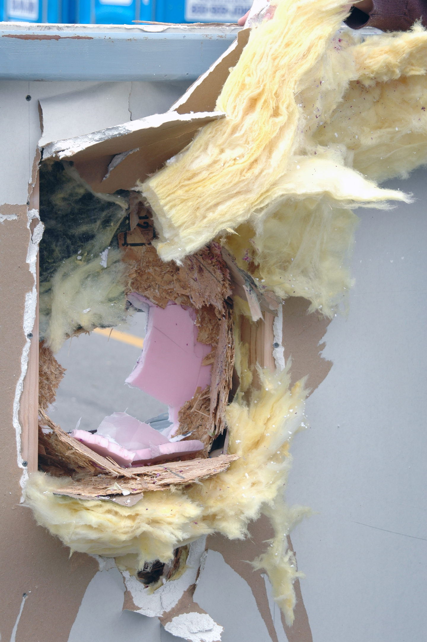
Good concrete consolidation is essential. Lack of consolidation can cause voids, rock pockets, honeycombing, and poor bonding with the rebar. In extreme cases, improper consolidation can affect the structural integrity of the walls.

On the other hand, excessive vibration can create bulged walls and blowouts.
How much vibration does an ICF wall need, and what is the best way to do it? Good consolidation is a combination of different factors, and vibration is only one of them. Suitable mix design and correct placement technique are critical, but are not discussed in this article. For more information on these topics, see Proper Concrete Placement in the February ’06 issue of this magazine. It’s available online at www.icfmag.com.

Vibration and ICFs is an area that generates significant controversy. ICF-related discussion forums reveal a broad range of opinions and method. In finding an effective solution for you, the principles below should provide general guidelines.

Modern Forms Are Strong
Much of the confusion over how to vibrate ICFs comes from outdated information. Today’s ICFs can withstand internal vibration, and nearly all manufacturers strongly encourage it. But that hasn’t always been the case. As recently as the late 1990’s, some ICF designs did not have the strength to handle adequate vibration. Contractors were advised to use orbital sanders, reciprocating saws with the blade removed, or even to “bang on the blocks with a short length of 2×4.”Unfortunately, these methods do not provide sufficient consolidation. Even more regrettably, these sub-par methods are still being used by some contractors.
Review an up-to-date installation manual or talk to the technical director at your preferred ICF company to get their latest recommendations about consolidation techniques. If these sources reveal that the form will not withstand internal vibration, consider switching to a more modern ICF design. Jobs with inadequate consolidation not only damage your reputation, but that of the entire industry.

Follow Published Guidelines
In 2003, the Portland Cement Association (PCA) conducted an in-depth study of concrete consolidation and ICFs. They tested flat panels with 4- and 6-inch cores, as well as a screen grid and waffle grid ICFs. Panels with corners and lintels were also tested. Test sections were filled with low- (3”), medium- (6”) and high-slump (8”-10”) concrete and vibrated with wood blocks, saws, sanders, and internal vibrators. They also filled test panels with a self-consolidating concrete (SCC).

In every case, walls filled with low-slump mixes had poor consolidation, regardless of the technique used. “External mechanical vibration using a hammer, reciprocating saw, or orbital sander did not significantly improve the consolidation of concrete in ICF walls…” the report states.

On the medium slump panels, external vibration scored slightly better, but not nearly as well as those that used an internal vibrator. High-slump concrete and SCC achieved adequate consolidation with minimal vibration.
The entire report, titled RD-134 Concrete Consolidation and the Potential for Voids in ICF Walls, is available for download from our website, or hard copies can be purchased from the PCA bookstore.

Additional guidelines for concrete consolidation are available under the American Concrete Institute’s ACI 318, and from various concrete vibrator manufacturers.

Internal Vibration Requires Trained Operators
The PCA report mentioned above concluded, “Internal vibration was found to provide adequate consolidation for concrete with a slump of 6 inches or greater… As an alternative to internal vibration, adequate consolidation also was achieved through the use of a flowable, high-slump concrete.”

Fred Oswald, president of * Industries, says it’s usually more cost-effective to vibrate conventional mix designs, since superplasticizers and SCC cost considerably more per yard. And the forms have to be almost watertight to hold the mix,” he adds.

“We recommend using a 3/4 inch diameter head for most ICFs,” Oswald says, “although it depends on the width of the form and the slump of the concrete. A stiff mix with a 4-inch slump needs a bigger head.” Even more important than correct equipment, though, is having a trained operator.

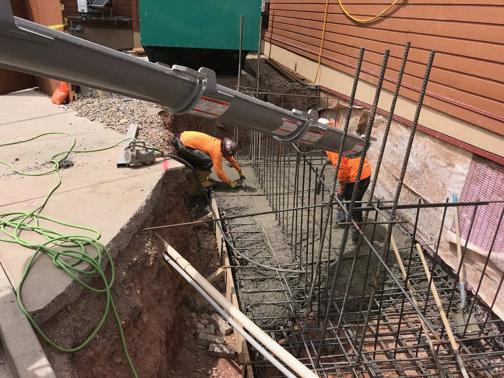
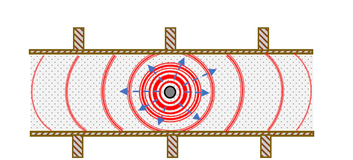
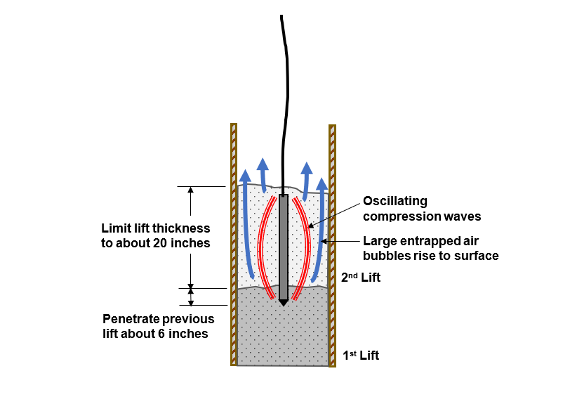
The vibrator should be inserted vertically into the mix, then slowly withdrawn. Vibrators work by allowing air to float up and out of the concrete, so the tip should not be withdrawn faster than the air can move upward, about 3 inches per second. If the wall is poured in multiple lifts, the vibrator tip should go deep enough to penetrate 3 to 6 in. into the previous layer.

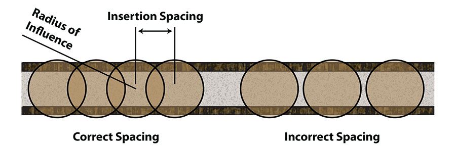
The vibrator has a “zone of influence” where consolidation is occurring. For proper consolidation, the operator needs to ensure the zones of influence overlap successively so that all areas of the concrete are properly consolidated. “It has to be done very systematically,” Oswald states.

Pay Attention to Corners and Lintels
Ironically, corners and lintels—the areas that need the most strength—are where poor consolidation is most likely to occur. That’s because these are the areas where reinforcing steel is most congested—and ICF forms are at their weakest. But these areas need more vibration, not less. Add extra bracing as needed; each form manufacturer has developed instruction on how to minimize corner movement, using a combination of plywood, zip ties, strapping tape, or additional bracing. Set an additional brace along each side of each window opening as well. Finally, note that the area below each window buck needs to be filled and vibrated separately.

Sizing the Vibrator
The PCA research on consolidation used a single internal vibrator. It had an amplitude of .08 mm and a ¾ inch head, giving an effective zone of influence six inches in diameter. Inserting the vibrator twice per linear foot of wall is tedious, and in many cases impractical. While no formal research has been done, here’s what those in the field say:

“A pencil [vibrator] doesn’t really get the job done,” a New York builder admits, “I use a 1 3/4” square head. Never had a problem with a blowout. The use of pencil vibrators started long ago because many of the old forms couldn’t take anything bigger. I’ve vibrated jobs with 2 1/2” a couple of times. Kinda increases the pucker factor, but I’ve had no problems.”

Eldon Howe, who has worked with ICFs for years in Michigan, says, “I’m using a 1.8 hp motor and a 1.5” head for a regular six-inch core. I’ve used a 1.5” head on a 14-foot whip with a 1.9 hp. motor [but] it seems a little much in a 6” wall. I believe it will work well in an eight-inch or thicker wall, though.”

Internal Vibration Requires Trained Operators
The PCA report mentioned above concluded, “Internal vibration was found to provide adequate consolidation for concrete with a slump of 6 inches or greater… As an alternative to internal vibration, adequate consolidation also was achieved through the use of a flowable, high-slump concrete.

Pay Attention to Corners and Lintels
Ironically, corners and lintels—the areas that need the most strength—are where poor consolidation is most likely to occur. That’s because these are the areas where reinforcing steel is most congested—and ICF forms are at their weakest. But these areas need more vibration, not less. Add extra bracing as needed; each form manufacturer has developed instruction on how to minimize corner movement, using a combination of plywood, zip ties, strapping tape, or additional bracing. Set an additional brace along each side of each window opening as well. Finally, note that the area below each window buck needs to be filled and vibrated separately.


CONSOLIDATION TIPS

• Start with a good mix. Most recommend a slump of at least 6 inches.
• Place material intelligently. Use a pump truck. A reducing hose can reduce splatter and increase efficiency.
• Brace corners and lintels well and vibrate them thoroughly.
• Consolidate carefully within the manufacturer’s guidelines.
• Internal vibration by a trained operator has proven most successful.

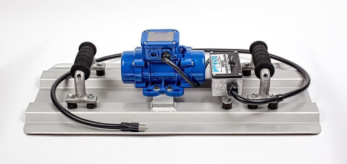
See Denver Concrete Vibrator’s handheld plate vibrator for Insulated Concrete Forms.

Return to Blog.

Read the article at ICF Magazine.
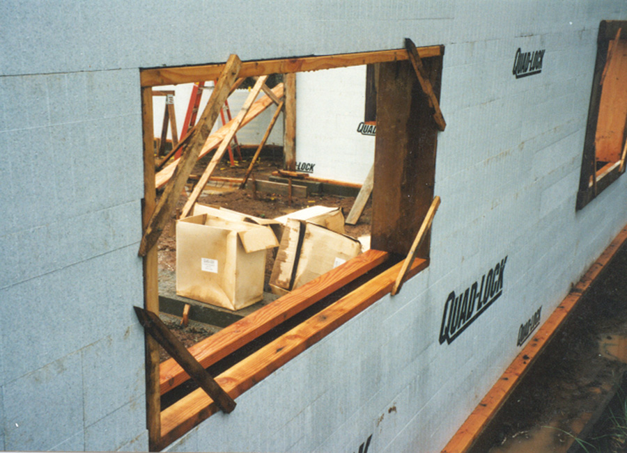
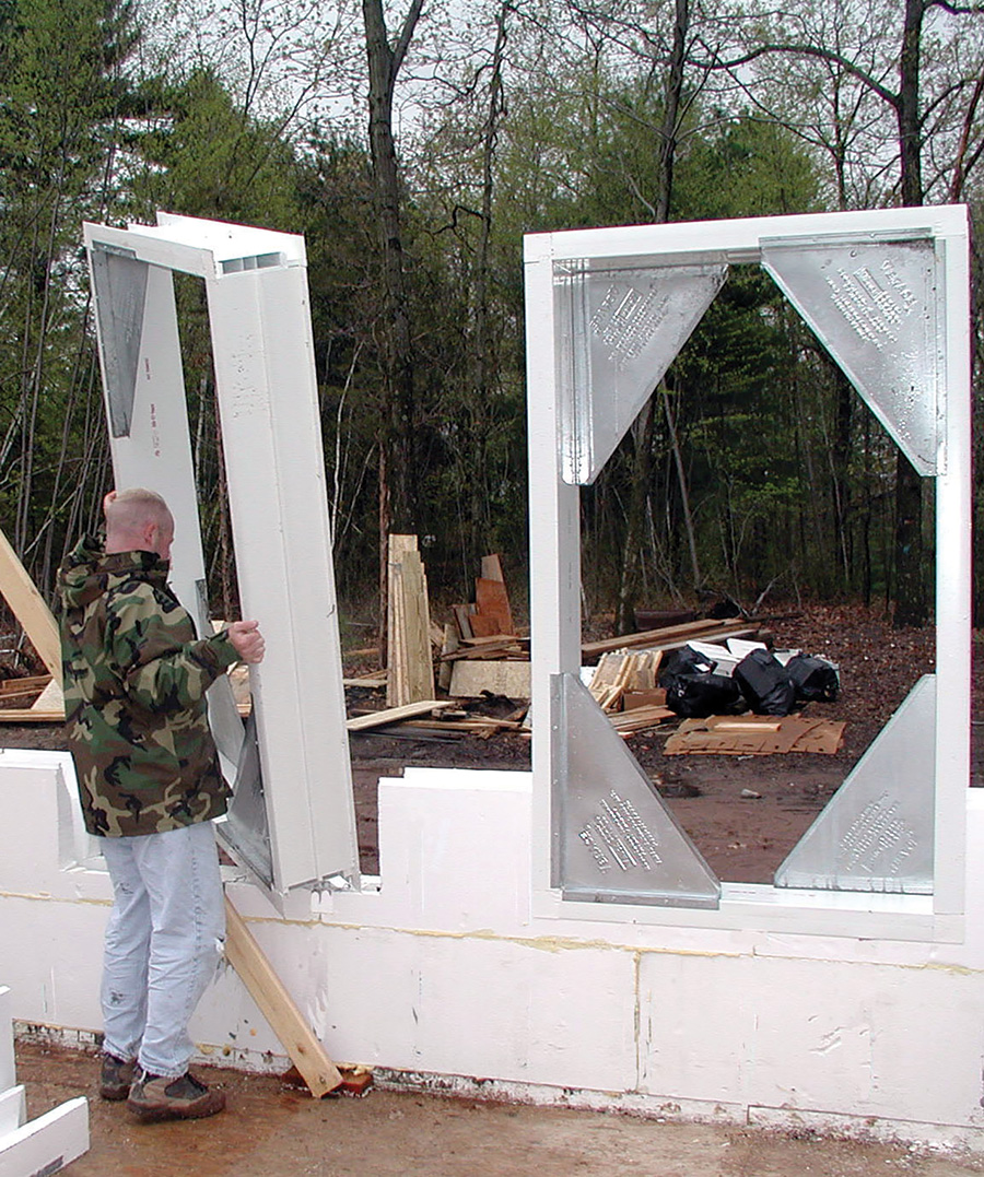
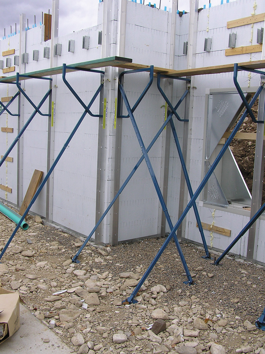
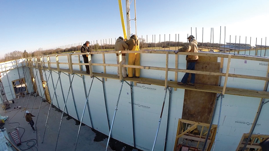
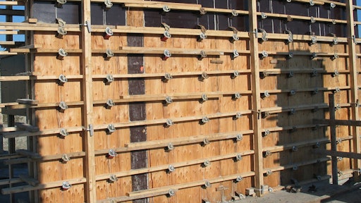
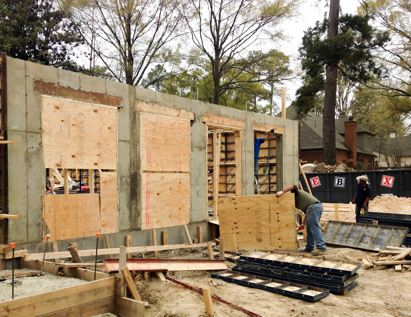
How Concrete is Made

Vibrator on batch plant

From the Portland Cement Association.

In its simplest form, concrete is a mixture of paste and aggregates, or rocks. The paste, composed of portland cement and water, coats the surface of the fine (small) and coarse (larger) aggregates. Through a chemical reaction called hydration, the paste hardens and gains strength to form the rock-like mass known as concrete.

Within this process lies the key to a remarkable trait of concrete: it’s plastic and malleable when newly mixed, strong and durable when hardened. These qualities explain why one material, concrete, can build skyscrapers, bridges, sidewalks and superhighways, houses and dams.

Proportioning

The key to achieving a strong, durable concrete rests in the careful proportioning and mixing of the ingredients. A mixture that does not have enough paste to fill all the voids between the aggregates will be difficult to place and will produce rough surfaces and porous concrete. A mixture with an excess of cement paste will be easy to place and will produce a smooth surface; however, the resulting concrete is not cost-effective and can more easily crack.

Portland cement’s chemistry comes to life in the presence of water. Cement and water form a paste that coats each particle of stone and sand—the aggregates. Through a chemical reaction called hydration, the cement paste hardens and gains strength.

The quality of the paste  determines the character of the concrete. The strength of the paste, in turn, depends on the ratio of water to cement. The water-cement ratio is the weight of the mixing water divided by the weight of the cement. High-quality concrete is produced by lowering the water-cement ratio as much as possible without sacrificing the workability of fresh concrete, allowing it to be properly placed, consolidated, and cured.

A properly designed mixture possesses the desired workability for the fresh concrete and the required durability and strength for the hardened concrete. Typically, a mix is about 10 to 15 percent cement, 60 to 75 percent aggregate and 15 to 20 percent water. Entrained air in many concrete mixes may also take up another 5 to 8 percent.

Other Ingredients

Almost any natural water that is drinkable and has no pronounced taste or odor may be used as mixing water for concrete. Excessive impurities in mixing water not only may affect setting time and concrete strength, but can also cause efflorescence, staining, corrosion of reinforcement, volume instability, and reduced durability. Concrete mixture specifications usually set limits on chlorides, sulfates, alkalis, and solids in mixing water unless tests can be performed to determine the effect the impurity has on the final concrete.

Although most drinking water is suitable for mixing  concrete, aggregates are chosen carefully. Aggregates comprise 60 to 75 percent of the total volume of concrete. The type and size of  aggregate used depends on the thickness and purpose of the final concrete product

Relatively thin building sections call for small coarse aggregate, though aggregates up to six inches in diameter have been used in large dams. A continuous gradation of particle sizes is desirable for efficient use of the paste. In addition, aggregates should be clean and free from any matter that might affect the quality of the concrete.

Hydration Begins

Soon after the aggregates, water, and the cement are combined, the mixture starts to harden. All portland cements are hydraulic cements that set and harden through a chemical reaction with water call hydration. During this reaction, a node forms on the surface of each cement particle. The node grows and expands until it links up with nodes from other cement particles or adheres to adjacent aggregates.

Once the concrete is thoroughly mixed and workable it should be placed in forms before the mixture becomes too stiff.

During placement, the concrete is consolidated to compact it within the forms and to eliminate potential flaws, such as honeycombs and air pockets.

For slabs, concrete is left to stand until the surface moisture film disappears, then  a wood or metal handfloat is used to smooth off the concrete. Floating produces a relatively even, but slightly rough, texture that has good slip resistance and is frequently used as a final finish for exterior slabs. If a smooth, hard, dense surface is required, floating is followed by steel troweling.

Curing begins after the exposed surfaces of the concrete have hardened sufficiently to resist marring. Curing ensures the continued hydration of the cement so that the concrete continues to gain strength. Concrete surfaces are cured by sprinkling with water fog, or by using moisture-retaining fabrics such as burlap or cotton mats. Other curing methods prevent evaporation of the water by sealing the surface with plastic or special sprays called curing compounds.

Special techniques are used for curing concrete during extremely cold or hot weather to protect the concrete. The longer the concrete is kept moist, the stronger and more durable it will become. The rate of hardening depends upon the composition and fineness of the cement, the mix proportions, and the moisture and temperature conditions. Concrete continues to get stronger as it gets older. Most of the hydration and strength gain take place within the first month of concrete’s life cycle, but hydration continues at a slower rate for many years.

Return to Blog.

Read the article on Cement.org